I missed Virtual Typex‘s launch back in March 2020, but a Cipher Mysteries review is better late than never, eh?
The short version: Virtual Typex is a gloriously techy bit of onscreen kit, that simulates all the moving components of a Typex cipher machine in a visually satisfying way. You’ll need a big monitor to see all the details properly (think UHD rather than HD), but as cipher machine simulations go it’s really nice-looking. (Though see the final section below for the caveat.)
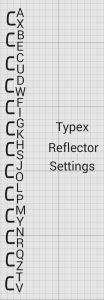
There’s an extensive set of help / introduction screens here, which both set the historical scene nicely and explain all the fiddly stuff to do with rotors, plugboards, and reflectors (and how Virtual Typex simulates them all). They don’t include any real Typex rotors (or rotor insert) settings, which is a huge shame (but I’m sure that Cipher Mysteries readers already knew that GCHQ aren’t likely to release anytime soon, bless ’em).
One nice piece of Typex history they got right (which I think may well be described here for the first time) is the wiring for the basic Typex reflector. This they managed to infer from an engineer’s Typex Mk III rotor-test cheat sheet when used with the pass-through rotor insert test set (and with the “DRUMS LOCKED AT AAAAA”:
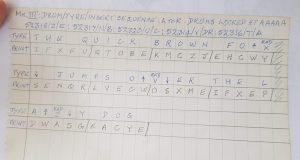
The discussion on the page continues:
[…] it is therefore possible to work out the reflector wiring for Typex as the [pass-through] rotors add nothing to the cipher in this case.
To do this, you’ll need one more piece of information, how the input & reflector heads (the connectors on either side of the rotors) are wired. The diagram above shows that on Typex, the input was wired reversed with respect to the reflector. This means that while A input pin is in line with the A reflector pin, B sits opposite Z, C-Y, D-X .. Z-B.
This, satisfyingly, then yields a Typex reflector mapping of:
As I said above, this is a really fantastic visualisation tool, that lets anyone who wants to try out a Typex for themselves (but without investing their pension on buying their own Mark 22 at auction, *sigh*).
However, it might not be correct. 🙁
Much as I like all the visuals and interactive side of VT, I’m going to be a huge spoilsport by suggesting as nicely as I can that I don’t think that this hasn’t yet been verified against a real Typex: and that anyone who relies on this as an actual simulation might well come a cropper. 🙁
The reason I think it’s incorrect is that if you (virtually) put any of the rotors with inserts in, and enter A twenty-six times (i.e. enough to rotate the first of the moving three rotors through a complete revolution), the next rotor along only clicks over five times (in an Enigma, it would click over once). Here’s the sequence of rotor settings you see onscreen in Virtual Typex:
- AAAAA
- AABAA
- AACAA
- AADAA
- AAEAA
- ABFAA <– i..e. the first time the second rotor along clicks over
- ABGAA
- ABHAA
- ABIAA
- ABJAA
- ABKAA
- ABLAA
- ACMAA<– the second time
- ACNAA
- ACOAA
- ACPAA
- ACQAA
- ACRAA
- ADSAA <– the third time
- ADTAA
- ADUAA
- ADVAA
- ADWAA
- ADXAA
- ADYAA
- AEZAA <– the fourth time
- BFAAA <– the fifth time
To my eyes, the problem is that the standard-issue empty rotor (i.e. the empty rotor that the inserts insert into) has nine triangular notches around its outside, not five. And it was my best understanding that it was these triangular notches that trigger the rotation in the next rotor along.
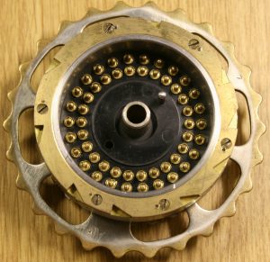
It’s always possible that I’ve got this basic physical detail wrong, but it’s certainly something that I’d like solidly checked before endorsing Virtual Typex as anything apart from beautiful cryptographical eye candy. :-/
PS: I also couldn’t help but get the impression that parts of the site’s historical documentation had been lifted unattributed from Cipher Mysteries, which is a bit cheeky. Just thought I’d say, hohum. :-/
Nick: There was more than one type of Typex rotor available with different numbers of step notches – there were 5, 7 or 9 and possibly 3, but each set would have the same number of notches.
GeorgeC: do you have a source for this? I recalled reading some years ago that only a single set of hollow rotors was ever used up until the end of WWII. All the photos of hollow rotors (including the ones on the Virtual Typex site) I’ve seen have had the same number of notches.
Nick: Take a look at the Rotors section of Jerry Procs website: http://www.jproc.ca/crypto/typex.html
and the Wheels section of this one: https://www.cryptomuseum.com/crypto/uk/typex/
GeorgeC: very interesting, there was even a 3-notch hollow rotor on display there. 🙂
However, I still recall reading that only a single reflector and a single hollow rotor was used for rotor inserts in the years up to 1945, so I will have to go back and look again at my sources. 🙁
Nick: I think the Enigma machine never made full use of the step notches specified in the original patent, and only ever used one configuration, but Typex did take advantage of the extra security provided by multiple stepping. One reason why Typex was never cracked ( that we know of ).
GeorgeC: the reason Nazi Germany didn’t really try to break Typex was because its cipher departments were spread out across many different parts of its war effort. It was Bletchley Park’s centralisation of effort that allowed the British to conceive of a technologically assisted solution.
Typex was already deemed relatively insecure by 1948, so it was entirely conceivable that the Germans would have been able to try.
Nick, firstly – it seems I owe Cipher Mysteries an apology! It wasn’t my intention to miss it out of my list of sources, but it appears that I have done just that! I will make that amend as soon as I get the chance – I hope you’ll forgive my lapse. Your link through to the British Navy Typex information was most informative and very helpful in trying to get my simulation as accurate as possible and can only think that I misplaced where I collected all the information.
You’ll find data on the multiple notches on Typex rotors on both http://www.jproc.ca/crypto/typex.html and https://www.cryptomuseum.com/crypto/uk/typex/ although, as you’ve pointed out, I do not have the information on the rotor wiring or notch positions for the original rotors so mine are just made up. Maybe GCHQ will release them one day!
I have checked my Typex simulation against GCHQ’s Typex model on https://gchq.github.io/CyberChef which they have written using their working machine, and I believe it matches correctly (but I’m happy to be proven wrong and I’ll try to amend if it seems I can do better!). I also assisted with a Lorenz SZ & Colossus recipe on their site as well which allowed me to cheekily ask them for the recorded audio from their working machine which I now have – the sounds on the simulation are the real audio from a working Typex (which I think is very cool!)
Thanks for posting a review about my site and simulation of Typex, I’m glad you enjoyed using it – it was a lot of work to do but I’m pretty pleased how it came out.
My latest project is a 3D, fully working, version of Colossus in a browser which I’m hoping to release later this year. https://twitter.com/VirtualColossus/status/1302168901351022592?s=19
Martin: I’ve had another go with your Virtual Typex just now and must admit to being a little confused by the reflector.
The hand-written document says that it is “locked” to AAAAA, which matches with the fact that all the spaces in “THE QUICK BROWN” etc get enciphered as E. Yet when I put the five test rotors in with the TPX-A reflector, even though Virtual Typex yields the correct output (“IFXEU” etc), the drum settings are stepping round as normal (they end up as BIYAA).
Is this a Virtual Typex display issue (allowing the rotors to rotate even though they are locked) rather than an enciphering one?
Nick: I think the “locked” to AAAAA is referring to setting the start positions of the rotors rather than them being physically locked. I guess it would be possible to adjust the bolt underneath each of the moving rotors to move the pawl away so it doesn’t turn the rotors, but if you’re testing the mechanism is fully working, I wouldn’t imaging there would be a point of offsetting the pawls, testing, then having to readjust the spacing back to where it would work on a normal rotor. From what I understand, the test rotors are not just to test the enciphering, but to check the whole machine is fully working, which must include the stepping mechanism being set correctly too!
If you check the images for the rotors which were owned by David White shown here: https://www.cryptomuseum.com/crypto/uk/typex/index.htm (which he confirmed were test ones – I think you can just make out TEST written on the end) and the ones taken by David Hamer here (http://jproc.ca/crypto/typex.html) you’ll see they are standard shaped rotors with the notches & stepping gear as on a normal rotor. This means the pawl will engage with the ratchet and step just like a standard rotor with each notch moving the next along as a key is pressed. If you check the end one on the far left of Mr.White’s ones – you can clearly see it has only 4 notches to step the next rotor on this one whereas Mr. Hamer’s photo shows 3 notches.
The only difference with the test rotors, I believe, is that rather than the wires being mixed and exchanging each letter for a different one as the rotors progress, these are wired straight through pin to pin. This must be the case for the test document to “encipher” as it does – any exchange of pins on any of the rotors would mean it likely that each specific letter would encipher as a different one as the rotors stepped but I’m pretty certain they did step as per a normal rotor.
Martin: sorry! Of course, if the inserts are wired straight through then it wouldn’t matter what the rotation position is, the net result would be the same! My mistake, thanks very much for having a look. 🙂
Martin Gillow: errrm… in proper Columbo style, I have “one last question” for you. 🙂
What is the default (i.e. non-plugboard) Typex right-hand entry mapping? I’ve tried to make sense of your clockwise/anticlockwise (relative to Enigma) description, but without success. 🙁 The reason I ask is that the “THE QUICK BROWN FOX” test sequence maps T to/from I, but the reflector map you give maps T to/from V, so an extra stage seems to be missing (which I guess must be the right-hand entry mapping). Thanks!
OK, I’ll try. The Typex is based on Enigma so lets assume we have an Enigma reflector and entry disc. Let’s name them wired A-Z in a clockwise direction when facing towards the entry disc and no changes to wiring on the plugboard. If all the rotors are wired direct through, then pressing key A on the keyboard would go to entry disc pin A, through all the rotors to reflector pin A, is reflected back (maybe to Y) which then goes through entry disc Y to type letter Y. The Typex, on the other hand, has the entry disc wired differently. Pin A is the same, typing a letter A will give a signal on pin A of the entry disc, but the rest are wired anti-clockwise. Typing a letter Z will give a signal on what we’ve called pin B, letter Y onto C and letter B will signal our pin Z. This is confirmed in the GCHQ CyberChef application which is available on GitHub and the Typex method they have written is tested against their real working Typex. It says “Typex input wiring is backwards vs Enigma: that is, letters enter the rotors in a clockwise order, vs. Enigma’s anticlockwise (or vice versa depending on which side you’re looking at it from) … Note that the wiring for the reflector is the same way around as Enigma, so no transformation is necessary on that side.” (https://github.com/gchq/CyberChef/blob/master/src/core/lib/Typex.mjs). We have to take this into account when working our document.
Input:ABCDEFGHIJKLMNOPQRSTUVWXYZ
Entry:AZYXWVUTSRQPONMLKJIHGFEDCB
Typing the letter T on the keyboard actually puts a signal on our named pin H which then travels through the direct-wired rotors to pin H on the reflector. To get our known output letter I typed, the reflector must signal back to entry disc pin S which will then type letter I. In my example, typing letter H signals entry pin T and therefore T is also the reflector pin. Therefore, the pin we need to type the letter F must be reflected back to entry pin V. I’m hoping that makes a little sense for you. Sorry if my wiring images are a little confusing, I drew them while on holiday on a mobile as I was too excited at working the reflector out to wait until I got home!
As far as I understand it, due to this security change in wiring, to make the Typex compatible with Enigma (as was used at Bletchley Park), we must undo this wiring reversal. The easiest way for them to have done this is by transposing the wiring back within the plugboard module when used in Enigma mode but having a straight wired one for use with Typex. This means they could easily switch between Typex & Enigma modes without having to get a soldering iron out!